This page provides direction for people interested in submitting their transformer requirements. Keep in mind, you’re always welcome to call in your specs or send them to us through the Quote Request page.
As you may expect, our design engineers gather a standard set of information when taking transformer requirements. If you are unable to locate any of this information, we may be able to help fill in the blanks. The following list describes each specification our engineers will request:
Input Voltage
This is the amount of voltage applied to the terminals of the primary winding of the transformer. If this is the voltage coming from your wall power outlet, it would likely be 110-120 volts (for North America) or 220-240 volts (for much of the rest of the world). North American industrial applications often use 220, 240, or 277 volts. Refer to the Worldwide Voltage & Frequency Standards for more detailed information.
Input Frequency
This is the frequency of the voltage applied to the terminals of the transformer’s primary winding. If your input power comes from your wall outlet, the likely input frequency would be 60 Hz (in North America) or 50 Hz (for much of the rest of the world). Refer to the Worldwide Voltage & Frequency Standards for more detailed information.
Output Voltage
This is the amount of voltage supplied by the transformer to the applied equipment. The equipment to be powered by the transformer will typically require a specific voltage and current for proper operation.
Output Current
This is the amount of amperage supplied by the transformer to the applied equipment. The output current (along with the output voltage) determines the output power.
Output Power (often referred to as "VA")
This is the output voltage multiplied by the output current, and it is the main determining factor when it comes to the physical size of the transformer (the greater the output power, the larger the physical size—for comparable construction types).
Because the voltage and current of the secondary circuit may not be in phase, the actual power delivered to the load may be lower than the VA (apparent power) rating.
Physical Size Requirements
As you would expect, there is a limit to how small a transformer can be built for a required output voltage and current. However, there are different configurations that may allow us to change the shape of the transformer so it might fit the available space or enclosure.
Mounting Method
This is the preferred way the transformer will be attached to the equipment, and there are three common methods:
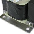
Chassis Mount
The transformer frame is mounted directly to the equipment, either by its frame or an attached bracket (shown).
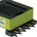
PCB Surface Mount
The transformer is mounted on a printed circuit board with pads (or feet) that are soldered directly to the surface of the board.
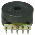
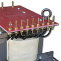
PCB Through-Hole Mount
The transformer is mounted on a printed circuit board with soldered pins that protrude through the board.
Termination Method
This is the preferred way the input and output windings will be terminated. The equipment to be powered by the transformer may also require a specific type of termination. The following termination types are commonly configured by Sun Transformer:

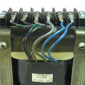
Wire Leads
Input and output lead wires are cut and stripped to desired lengths.
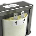
Quick Connects
The transformer has tinned-brass tabs of the desired size that are designed for quick connection/disconnection.
Terminal Board
The transformer has aligned screw-connects in desired order and size for easy wire or lug connection/disconnection.

Inline Connectors
The transformer leads are crimped to connectors inside plastic housings, which then fit mating connectors on the applied equipment.
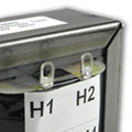
Bolt Terminals
The transformer has individual brass or stainless-steel bolts (usually 10-32 or ¼-20 size), one for each input and output lead. This is often the preferred termination method for power transformers over 2 KVA.
Solder Lugs
The transformer has tinned-brass tabs with holes to fit your specified wire size for easy soldering connections.
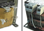
Screw Terminals
The transformer has individual screw-connects, one for each input and output lead. There are different types of terminals, such as finger-safe terminals (shown on right), which meet European standards.
Estimated Annual Usage
This information is good to know because it helps us determine material and price. As you would expect, the cost-per-transformer is likely to decrease with a higher annual usage amount.
Other Requirements
Some applications may require unique features, such as a Copper Quieting Band (as shown) to further reduce transformer noise.